YAR and YARP
Power boxes YARP-11 are designed for switching and protecting electrical circuits from overload currents and short-circuit currents. The series includes: YARP-11-31-54-UKHL3, YARP-11-35-54-UKHL3, YARP-11-37-54-UKHL3, YARP-11-39-54-UKHL3.
Purpose:
Power boxes YARP-11 are designed for switching and protecting electrical circuits from overload currents and short-circuit currents. The series includes: YARP-11-31-54-UKHL3, YARP-11-35-54-UKHL3, YARP-11-37-54-UKHL3, YARP-11-39-54-UKHL3.
Power boxes of the YARP-11 series are designed for switching and protecting electrical circuits from overload currents and short-circuit currents.
Main advantages:
Structure of the symbol:
YARP-11-XX-XX-XXXX
YARP - a box with a switch and fuses
11 - conditional series number
XX - conventional designation of the nominal current value:
31 - 100A;
35 - 250A;
37 - 400A;
39 - 630A.
XX - protection level according to GOST 14254
ХХХХ - conventional designation of climatic version and placement category according to GOST 15150
Technical characteristics of the YARP-11 boxes:
|
Name |
Nominal current Iном, A |
Nominal voltage Uном, in |
Switch type |
Fuse type |
Degree of protection |
Tires |
Seal |
|
YARP-11-31-54-UKHL3 |
100 |
380 |
VR3231-V31250 |
PPN-31 100 A (dimensions 00) |
IP54 |
3x25 |
PG29 |
|
YARP-11-35-54-UKHL3 |
250 |
380 |
VR3235-V31250 |
PPN-35 250 A (dimension 1) |
IP54 |
3x25 |
PG29 |
|
YARP-11-37-54-UKHL3 |
400 |
380 |
VR3237-B31250 |
PPN-37 400 A (dimension 2) |
IP54 |
4x40 |
PG29 |
|
YARP-11-39-54-UKHL3 |
630 |
380 |
VR3239-B31250 |
PPN-39 630 A (dimension 3) |
IP54 |
5x50 |
PG36 |
Schematic diagram of the power box:
Application areas – mechanical engineering and fuel and energy complexes, energy enterprises, housing and utilities, railway transport, nuclear power plant facilities. Installed:
● Directly on building structures;
● In ground-based stationary complete devices;
● Input and distribution devices of residential, public and industrial buildings, distribution cabinets and points, transformer substations, control cabinets and boxes, nuclear power plant facilities.
Operating conditions:
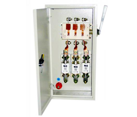
Design:
The low-voltage switchgear units are stationary low-voltage complete devices consisting of a metal casing in which a mounting panel is installed. The devices are placed on the panel. The design of the low-voltage switchgear unit ensures that the switching device is interlocked with the box door in such a way that when the switching device is on, the box door cannot be opened without breaking the interlock. The switching device is switched on and off using a drive handle installed on the side wall of the casing.
The operation of the low-voltage switchgear unit must be carried out in accordance with the requirements of the "Rules for the technical operation of consumer electrical installations". Switching the switching device of the low-voltage switchgear unit must be carried out with the box door closed. The box casing must be grounded in accordance with the requirements of GOST 12.2.007.0-75.
Overall dimensions:
Laying wires and cables in UVN cabinets that do not belong to this cabinet is not allowed. In exceptional cases, when fulfilling the requirement leads to a significant complication of installation or design, it is permissible to lay these wires and cables in pipes or boxes.
© «KazElectroSnab» LLP 2026. All rights reserved.