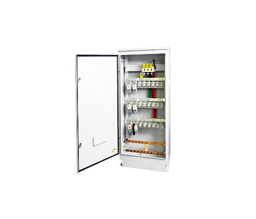
Distribution cabinet ШР-11-73511-22
Distribution cabinets of the ШР-11-73511-22 series are intended for use in AC networks with voltage up to 660 V and up to 400 V DC. The cabinets are designed for a rated current of up to 400 A. They are used in power supply systems of industrial enterprises, agricultural facilities, oil and gas fields, populated areas and residential buildings.
Purpose:
Distribution cabinets of the ШР-11-73511-22 series are designed for operation in AC networks with voltage up to 660 V and up to 400 V DC. The cabinets are designed for a rated current of up to 400 A. They are used in power supply systems of industrial enterprises, agricultural facilities, oil and gas fields, populated areas and residential buildings. Main technical characteristics:
The standard version of the product is manufactured in a metal case based on fuses PPN, switch-disconnector VR32, and other components of domestic production.
|
Parameter name |
Meaning |
|
Nominal current, A |
up to 630 |
|
Nominal voltage, V |
up to ~660, 50 Hz or =440 |
|
Climatic performance according to GOST 15150 |
UHL2, UHL4, U3 |
|
Category of application according to GOST 17516.1 |
AC-3 |
|
Nominal operating mode |
Long lasting |
|
Nominal insulation voltage Ui |
Corresponds to the rated voltage of the power circuit |
|
Type of internal division |
1 (no division) |
|
Type of electrical internal connections according to GOST R 51321.1-2000 |
FFF |
|
Type of grounding system |
TN-C (system with classic grounding) |
Input and output of external conductors is carried out from the bottom of the cabinet. Input and output cables must have cable lugs. At the input to the cabinet, it is possible to install a switch-disconnector for one or two directions, or a switch with fuses. By default, a switch-disconnector for one direction is installed. Cabinets are installed on the floor.
Products are classified:
Design:
Power distribution cabinets ШРС-1 and ШР-11 are assembled on the basis of ШР cases. Panels of the ШРС-1 and ШР-11 power distribution cabinet are a collapsible structure made of bent metal sections with input and switching and protective equipment installed on it. The cabinet body is equipped with an internal frame designed for installing a VR-32 type switch and PN-2, PPN-35, PP-35 type fuses. Electrical circuits inside the cabinet are implemented using a set of power buses. The design provides for the input and output of wires and cables from the bottom of the cabinet.
The cabinets are designed for rated currents of up to 400 A and rated voltage of up to 380 V three-phase alternating current with a frequency of 50 Hz with a solidly grounded neutral, as well as for protecting receiving lines and with protection of outgoing lines with fuses. Power is supplied from one or two independent power sources. Withstandable surge current:
- at the rated current of the cabinet of 250 A - not less than 10 kA;
- at the rated current of the cabinet of 400 A - not less than 25 kA.
Power cabinets SR have additional application options. Cabinets can contain the following modules: input module; distribution module; control module with input voltage indication; additional equipment.
The board bodies are made of sheet metal 1.2-1.5 mm thick with a polymer coating RAL7035 (gray). The input of supply wires and cables is provided at the bottom, and the output of outgoing wires or cables is down or up. For ease of cable entry, the cabinet is equipped with a 100 mm high base (on request). When ordering a low-voltage switchgear unit, the following is specified: setting the fuse tripping current, location of the switch drive on the left side wall of the cabinet, the presence of a bottom cover in cabinets with protection rating IP54, the number of glands for sealing cables indicating the cable diameter. Cabinets can be manufactured according to the customer's designs. To restrict access, the outer door of the panel has a latch lock with a key. The installation method is floor-standing. The degree of protection of the enclosures is IP31, IP44, IP54. Climatic version U3 and U2 according to GOST 15150-69. Panels are manufactured in accordance with TU RB.
The cabinet is a frameless metal case in which a switch and fuse boxes are installed. Each phase of the switch is connected to the fuse box using an aluminum busbar.
There is a removable cover on top. The door and the upper cover for cabinets with protection rating IP54 are sealed with a rubber cord. A neutral busbar is provided in the lower part of the case.
The design of the cabinets provides for: installation of the cabinet on the floor; input of supply conductors and output of outgoing conductors from above and below through a removable cover; output of the removable drive of the switch-type switch on the right (drive on the left upon request), for the version with fuses at the input - only on the right, and for cabinets with two switch-type switches - on the left and on the right; installation of fuses with and without an operation indicator; interlock, ensuring the impossibility of switching on two switch-type switches simultaneously.
- at a rated cabinet current of 250 A not less than 10 kA
- at a rated cabinet current of 400 A not less than 25 kA
Cabinets of the ЩРС1 and ЩР11 series are manufactured for use with TN-S, TN-C, TN-CS grounding systems according to GOST 30331.2 / GOST R 50571.2
Power cabinets ЩРС1 have additional application options, unlike ЩРС1 cabinets. Thus, in cabinets ЩРС11-73511 - ЩР11-73517, fuses PN2-400 (PPN37 400 A) are installed at the input, and in cabinets ЩР11-73518 - ЩР11-73523, two inputs are provided.
Structure of the symbol:
|
SR |
- |
11 |
- |
7 |
3 |
5 |
1 |
- |
0 |
54 |
|
|
|
|
|
|
|
|
|
|
|
|
|
1 |
|
2 |
|
3 |
4 |
5 |
6 |
|
7 |
8 |
|
1 - |
Distribution cabinet |
|
2 - |
Development number |
|
3 - |
Installation type - floor-standing, conductor input in any combination |
|
4 - |
Height of cabinet 1600 mm |
|
5 - |
Cabinet width: |
|
6 - |
Cabinet diagram number (01 to 23) |
|
7 - |
Degree of protection according to GOST |
|
8 - |
Climatic performance and placement category according to GOST 15543-70 |
If, during the period that has passed since the periodic tests were conducted, type tests were conducted related to changes in design, materials or production technology, then the periodic tests should be conducted only for those items of the periodic test program for which type tests were not conducted.
© «KazElectroSnab» LLP 2025. All rights reserved.