SHRS-1
Purpose:
Distribution cabinets of the ШРС-1-23 series are designed for operation in AC networks with voltage up to 660 V and up to 400 V DC. The cabinets are designed for a rated current of up to 400 A. They are used in power supply systems of industrial enterprises, agricultural facilities, oil and gas fields, settlements and residential buildings.
The structure of the conventional designation of ШРС-1(А) cabinets
ShRS – 1(A) – ХХ – XX ХХХ
|
ShRS – 1(A) – ХХ – XX ХХХ |
Distribution cabinet |
|
ShRS – 1 (A) – XX – XX XXX |
Modification number |
|
ShRS – 1(A) – ХХ – XX ХХХ |
Layout of the electrical circuit according to the table |
|
ShRS – 1(A) – ХХ – XX ХХХ |
Degree of protection of the shell: 31 – IP31; 54 – IP54 |
|
ShRS – 1(A) – ХХ – XX ХХХ |
Climate performance and accommodation category |
Device:
Most power cabinets of the ShRS are equipped with special fastening elements - DIN rails, which allow simple and quick installation of modular switching and protective devices. Special cable organizers and plastic boxes are intended for ergonomic and compact laying of wires and cables inside the cabinet. If there is a metering function, the power cabinet of the ShRU has a special viewing window.
Power distribution cabinet is an electrical device designed to control energy in group circuits. Such panels receive current with subsequent distribution to the system components. It is a metal or plastic box that hides switching equipment, meters and other network elements from prying eyes. Cables are supplied and removed through the provided openings, into which glands are mounted.
The fundamental idea of such equipment is to protect networks from short circuits and overloads. In addition, distribution boards perform the function of inputting power reserves, protect energy complexes from accidental interference from the outside, decorate walls, hiding unsightly buttons with their panel. Currently, distribution cabinets are included in all electrical networks, regardless of the purpose and scale of the facility. For each need, there are suitable modifications with convenient dimensions, components, color and design.
Features:
The cabinets of the ШР and ШРС series have a shell of a solid welded metal structure. It contains the equipment for the main and auxiliary distribution networks. The cabinet has a door that provides excellent access to all elements. But it is important to understand that this access is only possible with a special key.
Wires can be supplied to the device from above and below. In the lower part of the unit there are copper buses, with the help of which the protective and neutral conductors are connected.
If other units related to the provision of power supply are often produced in several versions, thanks to which you can use a design suitable for your interior, then ШРС is floor-standing equipment.
The walls of the equipment are very reliably insulated. With their help, good protection against electric shocks is provided if a short-term short circuit occurs.
Under what conditions is it possible to operate power distribution cabinets? The air temperature should be between minus four and plus forty degrees. It is also important to comply with the altitude requirements. It is not allowed to install the cabinet on sites that are no higher than two kilometers above sea level.
In addition, it is forbidden to install the SRS where the environment is explosive or contains aggressive gases, vapors that adversely affect the insulation of wires and the metal structure. It is very important to comply with these requirements, which will increase the service life and quality of operation of the devices.
The cabinets have galvanization that withstands current shocks of up to ten thousand amperes, while there will be no noticeable damage.
Scope of application:
Power distribution boards of the ЩРС type are used at industrial facilities and civil engineering facilities — distribution boards after the main switchboard at small power supply units (power supply to a floor, workshop, etc.), residential buildings, office centers.
The equipment used:
— OT type switches with mechanical reversing blocking for currents from 16 to 630 A;
— fuses PPN (up to 6ZA), PN2-100 (up to 100 A), PN2-250 (up to 250 A), PN2-400 (up to 400 A).
Design:
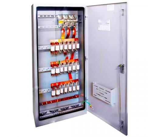
The SHRS-1 distribution cabinet is a metal case consisting of a front and rear frame assembly. The door opening angle is at least 95°. The cabinet is equipped with an internal frame on which a VR32 switch-disconnector and PPN type fuses are installed. In the lower part of the front frame, there is a ground busbar and a neutral working busbar connected to each other by a removable jumper. The input and output of the supply and outgoing cables is provided at the bottom. Electrical installation is carried out with buses. The power supply line is connected to the input switch, which is operated using a handle located on the right side wall of the cabinet. Outgoing lines are connected to the corresponding fuse groups. The degree of protection from the bottom of the cabinet is IP00. In devices with a protection degree of IP54, a polyurethane seal is applied to the door and a base with gland entries is installed. The cabinet door is locked with a lock.
The cabinets are welded metal structures, inside which the equipment of the main and auxiliary circuits is located. Access to the panel is provided from the facade through the door. Input of power cables and output of outgoing line wires can be carried out both from above and from below. The cabinet is manufactured in a floor-standing version.
The switchboard bodies are made of 1.2-1.5 mm thick sheet metal with RAL7035 (gray) polymer coating. The input of supply wires and cables is provided from below, and the output of outgoing wires or cables is downwards or upwards. For ease of cable input, the cabinet is equipped with a 100 mm high base (optional). When ordering a switchboard, the following is specified: setting the fuse tripping current, location of the switch drive on the left side wall of the cabinet, the presence of a bottom cover in cabinets with IP54 protection rating, the number of glands for sealing cables with an indication of the cable diameter. Cabinets can be manufactured according to diagrams provided by the customer. To restrict access, the outer door of the switchboard has a latch lock with a key. Floor-standing installation method. Degree of protection of shells IP31, IP44, IP54. Climatic version U3 and U2 according to GOST 15150-69. Shields are manufactured in accordance with TU RB.
The cabinet is a frameless metal case in which a switch and fuse boxes are installed. Each phase of the switch is connected to the fuse box using an aluminum busbar.
There is a removable cover on top. The door and the top cover for IP54 protection class cabinets are sealed with a rubber cord. A neutral busbar is provided in the lower part of the case.
The design of the cabinets provides for: installation of the cabinet on the floor; input of supply conductors and output of outgoing conductors from above and below through a removable cover; output of the removable drive of the switch-type switch on the right (drive on the left upon request), for the version with fuses at the input - only on the right, and for cabinets with two switch-type switches - on the left and on the right; installation of fuses with and without an operation indicator; interlock, ensuring the impossibility of switching on two switch-type switches simultaneously.
|
Name |
Overall dimensions (HxWxD), mm |
Number, current of feeder fuses |
Current of the input switch-disconnector |
Weight, not more than, kg |
|
|
ShRS1-00-5-31 |
1600x500x300 |
5xPPN-31 (63A) |
250A |
57 |
|
|
ShRS1-00-5-54 |
58 |
|
|||
|
ShRS1-01-5-31 |
5xPPN-31 (100A) |
64 |
|
||
|
ShRS1-01-5-54 |
65 |
|
|||
|
ShRS1-02-5-31 |
2xPPN-31 (63A) +3xPPN-31 (100A) |
61 |
|
||
|
ShRS1-02-5-54 |
62 |
|
|||
|
ШРС1-23 |
1600x700x300 |
8xPPN-31 (63A) |
400A |
72 |
|
|
ШРС1-53 |
73 |
|
|||
|
ShRS1-04-7-31 |
8xPPN-31 (100A) |
83 |
|
||
|
ShRS1-04-7-54 |
84 |
|
|||
|
ShRS1-05-7-31 |
4xPPN-31 (63A) +4xPPN-31 (100A) |
82 |
|
||
|
ShRS1-05-7-54 ShRS-1A-55 ShRS1-55 ShR-11-73509-22 |
83 |
|
|||
|
ShRS1-06-5-31 |
1600x500x300 |
5xPPN-35 (250A) |
400A |
76 |
|
|
ShRS1-06-5-54 |
85 |
|
|||
|
ShRS1-07-7-31 |
1600x700x300 |
3xPPN-35 (250A) +5xPPN-31 (100A) |
77 |
|
|
|
ShRS1-07-7-54 |
78 |
|
|||
|
ShRS1-08-7-31 ShRS-1A-28 ShRS1-28 ShR-11-73510-22 |
2xPPN-35 (250A) +4xPPN-31 (100A) +2xPPN-31 (63A) |
82 |
|
||
|
ShRS1-08-7-54 |
84 |
|
|||
|
ShRS1-09-7-31 |
8xPPN-35 (100A) |
86 |
|
||
|
ShRS1-09-7-54 |
87 |
|
|||
|
ShRS1-1&5-31 |
1600x500x300 |
2x1 II 1N-35 (250A) +3xPPN-31 (100A) |
81 |
|
|
|
ShRS1-10-5-54 |
|||||
|
82 |
|
||||
|
ShRS1-11-7-31 |
1600x700x300 |
2xPPN-35 (250A) +6ХPPN-31 (100A) |
80 |
|
|
|
ShRS1-11-7-54 |
81 |
|
Technical specifications:
|
Parameter name |
Meaning |
|
Nominal current, A |
up to 630 |
|
Nominal voltage, V |
up to ~660, 50 Hz or =440 |
|
Climatic performance according to GOST 15150 |
UHL2, UHL4, U3 |
|
Category of application according to GOST 17516.1 |
AC-3 |
|
Nominal operating mode |
Long lasting |
|
Nominal insulation voltage Ui |
Corresponds to the rated voltage of the power circuit |
|
Type of internal division |
1 (no division) |
|
Type of electrical internal connections according to GOST R 51321.1-2000 |
FFF |
|
Type of grounding system |
TN-C (system with classic grounding) |
The remote protection devices must be blocked in case of voltage circuit failure. Individual stages of the remote protection AT must be blocked in case of synchronous swings and asynchronous modes. It is permissible not to block the protection stages if they are tuned out from synchronous swings in time.
The KTP should be considered as having passed the test for electrodynamic and thermal resistance with a short-circuit current if there is no welding of contacts, spontaneous ejection of disconnector blades and disconnecting contacts, residual deformation of the busbar and its fasteners, excess of the temperature of current-carrying elements above permissible values and other damage that prevents normal operation of the KTP.
Fill out an application on the website, we will contact you shortly and answer all your questions.
© «KazElectroSnab» LLP 2026. All rights reserved.