YARP-11
Power boxes YARP-11 are designed for switching and protecting electrical circuits from overload currents and short-circuit currents. The series includes: YARP-11-31-54-UKHL3, YARP-11-35-54-UKHL3, YARP-11-37-54-UKHL3, YARP-11-39-54-UKHL3.
Purpose:
Power boxes YARP-11 are designed for switching and protecting electrical circuits from overload currents and short-circuit currents. The series includes: YARP-11-31-54-UKHL3, YARP-11-35-54-UKHL3, YARP-11-37-54-UKHL3, YARP-11-39-54-UKHL3.
Power boxes of the YARP-11 series are designed for switching and protecting electrical circuits from overload currents and short-circuit currents.
Main advantages:
Structure of the symbol:
YARP-11-XX-XX-XXXX
YARP - a box with a switch and fuses
11 - conditional series number
XX - conventional designation of the nominal current value:
31 - 100A;
35 - 250A;
37 - 400A;
39 - 630A.
XX - protection level according to GOST 14254
ХХХХ - conventional designation of climatic version and placement category according to GOST 15150
Technical characteristics of the YARP-11 boxes:
|
Name |
Nominal current Iном, A |
Nominal voltage Uном, in |
Switch type |
Fuse type |
Degree of protection |
Tires |
Seal |
|
YARP-11-31-54-UKHL3 |
100 |
380 |
VR3231-V31250 |
PPN-31 100 A (dimensions 00) |
IP54 |
3x25 |
PG29 |
|
YARP-11-35-54-UKHL3 |
250 |
380 |
VR3235-V31250 |
PPN-35 250 A (dimension 1) |
IP54 |
3x25 |
PG29 |
|
YARP-11-37-54-UKHL3 |
400 |
380 |
VR3237-B31250 |
PPN-37 400 A (dimension 2) |
IP54 |
4x40 |
PG29 |
|
YARP-11-39-54-UKHL3 |
630 |
380 |
VR3239-B31250 |
PPN-39 630 A (dimension 3) |
IP54 |
5x50 |
PG36 |
Schematic diagram of the power box:
Application areas – mechanical engineering and fuel and energy complexes, energy enterprises, housing and utilities, railway transport, nuclear power plant facilities. Installed:
● Directly on building structures;
● In ground-based stationary complete devices;
● Input and distribution devices of residential, public and industrial buildings, distribution cabinets and points, transformer substations, control cabinets and boxes, nuclear power plant facilities.
Operating conditions:
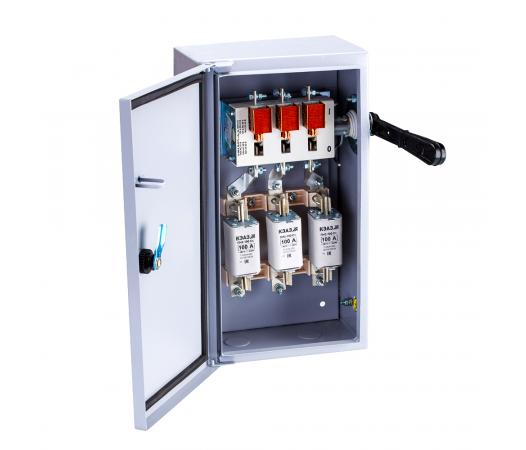
Design:
NKU are stationary low-voltage complete devices consisting of a metal casing in which a mounting panel is installed. The devices are placed on the panel. The NKU design ensures that the switching device is interlocked with the drawer door in such a way that when the switching device is on, the drawer door cannot be opened without breaking the interlock. The switching device is switched on and off using a drive handle installed on the side wall of the casing. The
NKU must be operated in accordance with the requirements of the "Rules for the Technical Operation of Consumer Electrical Installations". Switching the NKU switching device on and off must be performed with the drawer door closed. The drawer casing must be grounded in accordance with the requirements of GOST 12.2.007.0-75.
Overall dimensions:
It is not allowed to lay wires and cables in UVN cabinets that do not belong to this cabinet. In exceptional cases, when fulfilling the requirement leads to a significant complication of installation or design, it is permissible to lay these wires and cables in pipes or boxes.
© «KazElectroSnab» LLP 2026. All rights reserved.